Why am I getting different resistance measurements on a ESD tray?
Someone asked a question regarding measuring a tray with 2 different resistance instruments and getting totally different readings. The tray being used for the measurements was an uneven tray.
Without knowing the details of the tray, its conductive loading, particulate versus fiber, injection molded versus vacuum formed, I can only give some insight into understanding how different fixtures work with conductive polymer loads. They are as different as Apples and Oranges. There are many reasons for the possible difference in displayed readings on these two different instruments:
- Carbon or fiber loaded polymers are not always homogeneous and often provide irregular measurements
- Different parallel bar materials provide dramatically different measurements
- Metal contacts do not always make contact with the conductive particles or fibers at, or slightly below the surface of the material
- Machined metal contact surfaces make contact with the tallest particles on the surface of a material under test (MUT)
- Consequently, metal contact surfaces tend to indicate what the metal portion of a device will see when in contact with the MUT
- Soft rubberized contact surfaces conform more readily to irregular MUT surfaces and will easily make contact with conductive particles at or near the surface
- Soft contact surfaces indicate the optimal potential performance of a conductive material load, but do not necessarily represent what a device with metal contacts will see.
Also parallel bar instruments are intended to measure flat, regular material surfaces and are intended to measure the effect of many parallel paths across the material between the two bars. Using these instruments for Point to Point measurements are different than area measurements and will provide different measurement results. In this case they are simply indicators and not specification measurements.
For example, the ESD Check ESI-870 is probably just fine. You can check it by placing it on surfaces of various resistance characteristics e.g., on an insulated surface and a clean metal surface. The problem is when comparing two different measurement fixtures on an undefined surface – Soft Rubber vs Machined Metal contact fixtures – and expect to get the same answer. This is not always possible. This is the reason Prostat provides REMOVABLE conductive boots &
rings with its micro probes – the PRF-922B, PRF-912B, etc.
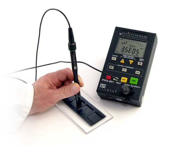 We provide these boots and rings because of the great variability in conductive loaded polymers. They are necessary to define the characteristics of the material’s surface resistance:
- Assuming a PRF-922B fixture, measure a conductive tray with the boots on and record the measurement(s). Do not use excessive pressure.
- Then remove the boots and measure the same area, and record the measurement(s). Do not use excessive pressure.
- If the two measurement sets are very similar, the conductive loading in the polymer is quite homogeneous. If both measurements are within desired range, the tray material process and forming is good, and acceptable.
- If the two measurements are quite different – i.e., 2 to 3 decades or more apart – the conductive loading in the polymer is NOT homogeneous, or there are surface characteristics that inhibit the materials dissipative performance. The measurements WITHOUT the soft conductive boots is most likely what a device’s leads will see when in contact with the material’s surface.
- The measurements WITH the soft conductive boots is how the material will perform when a soft conductive device makes contact with it. Most electronic devices are not soft, so the measurement without comparison to that without the conductive rubber is not very valuable. These measurements are typically used the indicate the material’s dissipative performance characteristics to the end user.
Again, check with the ESI-870 on different flat materials and you will see whether it is functioning correctly, or not. Simply hold it in the air and press the TEST button. It should indicate high or over level. Then place it on a clean metal surface and it should indicate its lowest measurement. If all is well, nothing is wrong with the instrument. It is not better or worse than any other indicating instrument: They are indicators, not specification measurements. You need to know how to use them and understand the differences in fixture contact surfaces.
Recent Comments